

The digital multimeter is one of the most widely used test instruments. A handheld DMM typically has 3½ or 4½ digit resolution and at least 3, but sometimes more than 10 functions (DCV, ACV, Ω, DCA, ACA, Hz, duty cycle, capacitance, continuity, diode test, etc). 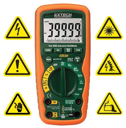 Newer meters include many features to increase safety, versatility and ease of use. However, proper operation is critical to safe and accurate measurements. Here are some common mistakes which can lead to bad readings, meter damage or harm to the user.
Measuring voltage with leads plugged into the amps terminals. Most meters have a separate input for current measurements which places a low-value resistor in series with the test leads. If the leads are left in these terminals when attempting to make a voltage measurement, a high current may flow through the meter. This can damage the device being tested and may blow the DMM’s internal fuse. If the source voltage exceeds the fuse rating, the overload may cause arcing, damage to the meter or operator injury. For this reason, some industrial meters use a fuse rated at 600V or 1000V rather than 250V.
Measuring current with leads in the volts terminals. If the test leads are left in the volts terminals while attempting to make a current measurement, the high meter impedance (typically 10 MΩ is placed in series with the leads. While not likely to damage the meter, this will decrease the current flow in the circuit under test and generate invalid readings. In a control circuit, it may cause unexpected operations.
Exceeding the rated input voltage. Most handheld DMMs show the maximum input voltage on the front label. This limit applies from input high to common and from either terminal to earth. Exceeding this rating can damage the meter and create a shock hazard. However, some measurement functions may have a lower protection level. For example, a meter with a 1000V rating on DC or AC volts may have a 300V or 600V limit on the Ohms function. On this type of meter, switching to ohms when measuring high voltage can damage the meter and create a shock hazard.
Trying to measure the resistance on a live circuit. In the ohms function, any voltage in the circuit under test invalidates the resistance reading. Usually this happens when power is still connected, but also can result from a stored charge in the circuit. A good practice is to check for AC or DC voltage before making an ohms measurement. Some advanced meters automatically perform this test and alert the operator if a voltage is detected.
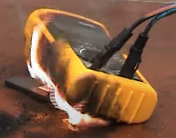 Using the wrong fuse for amps protection. It is important to match not only the ampere rating but also the type and voltage rating. Even replacing a fast blow fuse with a slow blow part of the correct amperage can result in meter damage before the fuse clears an overload. A more serious error is bypassing the fuse with a piece of foil or wire jumper. This loss of protection can lead to melted leads, fire and serious injury.
Ignoring lead resistance when making low resistance measurements. The 200Ω range on a 4½ digit meter has 10mΩ resolution. Test leads can add 30 counts or more of offset, which is significant when measuring motor windings, heating elements and other low resistance components. Some meters have a feature to null out this offset (like the zero adjust on analog VOMs), but that can lead to another problem.
Forgetting that an offset has been stored. If the meter has a Relative or Offset feature, the display shows the difference between the actual value and the stored offset. Most meters have an annunciator that lights when operating in this mode, but it can be easily overlooked.
Ignoring meter burden (loading). Most voltage measurements are made on circuits with a low source impedance (<1kΩ), so connecting the meter has little effect on the circuit. However, if the source impedance is 10kΩ and the DMM input is 10MΩ accuracy will be degraded by 0.1%. For a 3½ digit meter with a 0.2% basic accuracy, this is a significant additional error. On a 4½ digit meter with <0.1% accuracy, this is the largest error source.
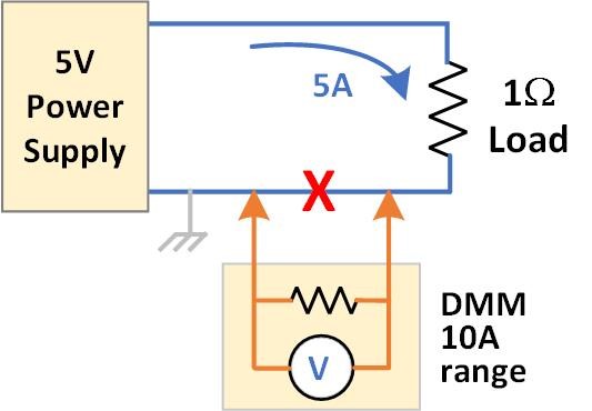 For current measurements, the meter burden can also have a major impact. In the amps function, connecting the DMM places a resistor in series with the load. This can significantly alter circuit operation. For example: a 5V supply provides 5A to a 1Ω load. This DMM specifies a 400mV burden on the 10A range, so there is 200mV across the meter at 5A. Due to the meter resistance, the circuit now draws only 4.8A. Since the DMM spec applies at the input terminals, any test lead resistance will further reduce the current. Meter burden on mA ranges can also be significant. An inexpensive DMMs may have a 1V burden on the 20mA range. Inserting this meter in a low voltage circuit will reduce the current in a similar manner to the 5A example. The meter burden can be reduced by switching to a higher range with a lower series resistance. However, this decreases the display resolution. The ‘of range’ part of the accuracy spec (±x digits) becomes a larger contributor to overall accuracy.
Misreading mV as Volts on an auto-ranging meter. Using diode check on high brightness LEDs. Autoranging is a convenient feature when the expected signal level is unknown or varies. However, this capability must be used carefully. The typical DMM has an annunciator to identify millivolt readings. This small annunciator can easily be overlooked, particularly if the digital value displayed is around the expected value. For example, if the expected reading is around 10V, then a residual voltage reading of 10mV can easily be misread as the expected signal. To prevent this error, many auto-ranging meters also allow the range to be set manually.
Misinterpreting noise from an open ACV input as a valid reading. Most DMMs have an input resistance of 10MΩ on the ACV function. A few pf of stray capacitance can cause a reading of 10V or more from a nearby 120V mains circuit. This is sometimes referred to as a ghost reading. The NCV (non-contact voltage) function relies on this effect to detect the presence of AC voltage. However, a ghost reading is not a valid signal level. Operator safety is also at risk if, due to poor probe contact, a circuit with hazardous voltage is thought to have a safe voltage level. The LoZ mode on some meters decreases the input resistance to 500kΩ or less, to eliminate ghost readings.
The typical diode check circuit in a DMM sources 1.5-3V. This is adequate to check silicon diodes, darlington transistors, and many LEDs. However, white and blue LEDs need more than 3 volts forward bias. A simple way to verify that the meter has adequate voltage is to test a known good LED.
Using an inadequate CAT rating. The measurement category (CAT) rating specifies where the meter can be safely used. Briefly, CAT II is for single-phase receptacle-connected loads & low-voltage mains circuits. CAT III is for three-phase distribution, single-phase commercial lighting and short branch circuits. CAT IV covers the utility connection, service entrance & any outdoor conductors. A maximum voltage level always accompanies the category level (e.g. CAT III 600V). A meter that can measure up to 1000V may only be rated for a maximum of 600V in a CAT III application and not be appropriate for use in any CAT IV location.
This brief article describes only a few of the more common problems that can occur when using a DMM. It is important to read the manual to become familiar with a meter’s capabilities, operation, and safe application. Inspect the test leads for finger guards, shrouded input connectors, adequate voltage rating, and good insulation before use. Wear safety glasses and other protective equipment when testing any circuit involving hazardous voltages or high currents. Remember the old electrician’s adage – keep one hand in your pocket.